How to Configure RIP on Juniper in GNS3 1.1

Run Routing Information Protocol on JunOS 12.1 in GNS3:

In this article i will show you how to run the RIP (Routing Information Protocol) among juniper routers. when you configure the RIP on junos by default it will enable RIP v2 & this is one of the difference from Cisco where you need to configure version2 manually.
I have simulated this lab on gns3 which is one famous network simulator. For juniper simulation i have used junos olive only for study purpose and junos olive is not suitable for any type of commercial use. Gns3 Labs detail are as mention below but you can use any versions of these software.

Gns3 version= Gns3 1.1
Junos version=  JunOS Olive 12.1 VM image
VM VirtualBox version=  4.2.4 

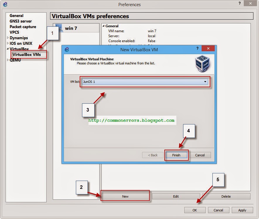
If you want learn more about the configuration of junos in gns3 you can visit how to configure junos on gns3 and Juniper commands.


Lab Requirements:
There are three Junos routers in given topology which are connected with each other and already configured with correct IP addresses according to topology. If you want to explore how to configure IP addresses to JunOS interfaces you can visit IP & static routing on JunOS. We have the following task for this Gns3 Lab:

  • Configure RIP routing protocol on all these routers


Explanation:
Configuration of RIP on junOS is very simple, you need only few commands and then good to go..:).
By default JunOS don't advertise RIP routes & the routes received from neighbors, so we need to define a routing policy for advertisement of RIP routes.

Configuration of RIP on JunOS2:  

You can start configuring JunOS2 in following way.

login: root
root@% Cli
root > configure
[edit]
root # set protocols rip group rip-routes neighbor em0 

where rip-routes is the group name, which you can set it of own choice and em0 is the connected interface of Junos2.

root #set policy-options policy-statement advertise-RIProutes from protocol direct
root #set policy-options policy-statement advertise-RIProutes from protocol rip
root #set policy-options policy-statement advertise-RIProutes then accept

Where "advertise-RIProutes" is the name of policy. now you need to apply this policy with following command.
root # set protocols rip group rip-routes export advertise-RIProutes
root # commit
Useful link: how to save current configuration in junos.

RIP Configuration  on JunOS3: 

root
Cli
configure
set protocols rip group rip-routes neighbor em0 
set protocols rip group rip-routes neighbor em1

Set policy-options policy-statement advertise-RIProutes from protocol direct
set policy-options policy-statement advertise-RIProutes from protocol rip
set policy-options policy-statement advertise-RIProutes then accept
set protocols rip group rip-routes export advertise-RIProutes
 commit

RIP Configuration  on JunOS4: 

root
Cli
configure
set protocols rip group rip-routes neighbor em0

Set policy-options policy-statement advertise-RIProutes from protocol direct
set policy-options policy-statement advertise-RIProutes from protocol rip
set policy-options policy-statement advertise-RIProutes then accept
set protocols rip group rip-routes export advertise-RIProutes
 commit
How to verify configuration:

You can test your configuration by ping from junos2 to 222.0.0.1 which is a loopback address on junos4. Also "show route" will show all routes on all routers. An output of show route command will have the following routes:


How to Configure Static routing on juniper router in gns3

Junos static route configuration:

In this article i will show you how to configure static routing with junier router on gns3. For configuring static routing you need to define the route as static and with a next-hop address with it. 


Please note this lab is performed only for study and practice purposes using Junos olive , which is unsupported and unsupportable platform & it is not suitable for any type of commercial use.
Lab Requirements
You have three juniper routers connected with each other, you have the following tasks to perform:
  • Configure all the interfaces with right IP address (According to figure)
  • Configure static routes between all routers so that they can communicate with each other.
Other Detail:
Junos image versionJunOS Olive image 12.1 
Gns3 version= Gns3 1.1 (you can use any version)
VM VirtualBox version=  4.2.4 (you can use any version)

you can visit how to configure junos on gns3 and Basic JunOS commands.

Set IP addresses of all interfaces of juniper router:

For setting ip address of interface you need the following commands.

JunOs2 configuration:
login: root
root@% Cli
root > configure
[edit]
root # set interfaces em0 unit 0 family inet address 172.16.1.1/24

You can also configure some loopback with these commands:

root # set interfaces lo0 unit 55 family inet address 111.0.0.1/32
root # commit

Having issue with commit command visit missing mandatory statement'root-authentication'


JunOs3 configuration:
Cli
configure
set interfaces em0 unit 0 family inet address 172.16.1.2/24
set interfaces em1 unit 0 family inet address 192.168.1.1/24
commit

JunOs4 configuration:
Cli
configure
set interfaces em0 unit 0 family inet address 192.168.1.2/24

You can also configure some loopback with these commands:

set interfaces lo0 unit 55 family inet address 222.0.0.1/32

commit

Configure static routing on Juniper routers:

For configuration of static routing you need next hope addresses:
Static routing on JunOs2 
On junos2 111.0.0.1/32 and 172.16.1.0/24 are directly connected networks whereas 192.168.1.1/24 and 222.0.0.1/32 are remote or destination networks and inaccessible from junos2 . You need to configure static routes for making these routes accessible on junos2. Nex-hop address is 172.16.1.2 for all these routes.          

Cli
configure
set routing-options static route 192.168.1.0/24 next-hop 172.16.1.2
set routing-options static route 222.0.0.0/32 next-hop 172.16.1.2

Static routing on JunOs3
111.0.0.1/32 and 222.0.0.1/32 are inaccessible networks on junos3 and need static routes. Nex-hop addresses are 172.16.1.1 for 111.0.0.1/32 and 192.168.1.2 for 222.0.0.1/32.

Cli
configure
set routing-options static route 222.0.0.0/32 next-hop 172.16.1.1
set routing-options static route 111.0.0.0/32 next-hop 192.168.1.2

Static routing on JunOs4
Nex-hop address for all routes on junos4 is 192.168.1.1.          

Cli
configure
set routing-options static route 172.16.1.0/24 next-hop 192.168.1.1
set routing-options static route 111.0.0.0/32 next-hop 192.168.1.1

Testing:
You can verify your configurations with following results:

Ping from junos2 to 222.0.0.1 should be successful.


Show route brief on JunOS 4 will have following output 


Juniper error missing mandatory statement 'root-authentication' | requie change of case, digit or punctuation

error: comit failed: (missing statements) Commit command is not working | how to save running configuration on juniper in gns3:

Error Message detail:
Junos version= JunOS Olive 12.1R1.9
error messge= missing mandatory statement 'root-authentication'
error image=

The reason or causes of this error:
  juniper router running JunOs have the default user name "root" with not password. Whenever you want to commit or save some changes/configuration using commit command & no password is set for root user then it will show you the above error that is "missing mandatory statement 'root-authentication' "

How to save current configuration on Juniper:

In order to commit change or for saving current configuration on juniper router you have to set the root password. You can set the root password on juniper router with following commands:

cli
configure

set system root-authentication plain-text-password (press enter)
now type the root password and press enter. Remember you are required to set a strong password with alpha numeric characters otherwise it will show you error messages
error: minimum password length is 6
error: requie change of case, digit or punctuation 
 and you will need another try with a password having letters and numbers..


once you have  successfully set root password, now you will able to save the current configurations & your commit command will also works fine. If you want explore Juniper commands and want to learn more about configuration of juniper on gns3


How to Email or upload .exe with gmail | Blocked for security reasons!

How to upload an executable and others files those are Blocked for security reasons using Gmail:

As a security reason to save you from viruses and from other malicious software Gmail has blocked  to send or receive  .exe files. Similarly you can't send zip file having executable files or .rar file within a .rar or zip file.
wherever you upload such file you get the message "Blocked for security reasons! "

If you need to email an executable file (.exe) and you know that this is not a harmful file, you can send it by following method.

On windows 8:

Step 1-Show file extensions: If your operating system is windows 8 then open the folder that have the exe file which you want to email. Then from view tab check the checkbox "file name extensions ". this will show file extensions.


Step 2-rename file and remove extension: now right click on file and rename, remove .exe from it.
Windows will confirm from you click on yes.


Now you have an unrecognized file, you can attach this to gmail easily without any error message and receiver of this email can use this file by adding .exe extension using above method.


On windows 7:
On windows 7 you can send the executable file with same method but showing file extensions is a little different. You can show the file extensions on windows 7 by following steps:

Open the organize\folder and search option from file explore.

and then from view tab unclear the checkbox "hide extensions for known files' and click on OK.


now remove the .exe extension from file. In this way you can email an executable file using gmail.

Run / configure Juniper router Image with GNS3 1.1 junOS with VortualBox

How to use juniper Router on GNS3 1.1 using VirtualBox:

This article is about the installation and configuration of juniper router on gns3 1.1. There are some ways for using Juniper router on GNS3, here i will discus one of them i.e. using VM junOS on GNS3.  

In this method we used a virtual machine of JunOS Olive (Juniper Image) for gns3 simulation. You need the following software for this:
  1. juniper image= JunOS Olive image VM (.ova filewhich you can download from this link. 
  2. Pre Installed Gns3 
  3. Pre Installed Oracle VM VirtualBox (You can download it free from internet)
Once you have downloaded  JunOS Olive image from given link and after the installation of Oracle VM VirtualBox, you need to create a virtual machine using this .ova file in your virtual box and then you can use that VM in GNS3 for simulating juniper router. You can install

1. Simply double click on this  .ova file that you have downloaded from above link or open this file using virtual-box and then click on import. You can change default setting before importing, for example you can change the RAM, VM name, Network adapter etc
If you want to simulate more than one router in GNS3 then you need to create more than one copies of this JunOS VM instance or clone. For creating clone right click on  already created VM and then click on clone.

Then type the name for new clone or VM and select the checkbox "reinitialize the MAC address of all network cards"
In this way you can create multiple clone and can use multiple juniper router on gns3.
2. Now launch Gns3 and open the Edit\preferences, goto virtualbox setting and create a new VM on gns3 by clicking on New. select the junOS VM from menu that we have created in step-1 and click on finish and then on OK.

For using multiple juniper router you need to create multiple router VM  in gns3 using above method. For simulating three juniper router you need three VirtualBox VMs in Gns3. 

3. This juniper router VM will appear in end device menu of gns3.

You can set number of interfaces for this JunOS VM, for this drag VM on gns3 dashboard and then right click on it, click on configure and from network tab set the number of adapters or choose the interface type.
Now start the VM by right click on device and then on start, for configuration right click on it and then console. If you have any issue with the console then you can use the virtualBox console. User name is root for this junOS VM.

You can also change it PC symbol to router from change symbol.

Configure RIP on JunOS

Watch a Video:


Download and Run juniper router (junOS image... by Waqasgk

Download Juniper router IOS/Image for Gns3 JunOS Olive 12.1R1.9

Download VirtualBox Image (IOS) of Juniper Router for GNS3:

From here you can download "JunOS Olive 12.1" VM image, you can run it with GNS3 for simulating juniper router. (Please note that this image is only provide to you for informational purpose and for GNS3 use.)

What is JunOS Olive?
JunOS Olive is a software that you can use on PC. Initially Olive was used by Juniper internally for lab work, but now it become a source to learn the JUNOS CLI on a low-cost platform. Please note Junos olive is only for study and practice purposes , which is unsupported and unsupportable platform & it is not suitable for any type of commercial use.
Download JunOS forGNS3:
You can actually run this JunOS on VirtualBox and then can simulate this into GNS3. You can Download this JunOS for Gns3 from following link and can perform and configure different lab on Gns3.


Download JunOS olive Gns3


Juniper JunOS Download Link 2


Click on above link and then choose "download anyway" for download this file.


How to use JunOS Olive on Gns3


ICND2 VTP GNS3 Configuration LAB

How to configure Vlan Trunking Protocol on Gns3

Question
This GNS3 lab is related to VLAN Trunk Protocol, in which you have two switches Switch-1 and Switch-2 and you need to configure the Switch-2 according to following requirement:
  1. Determine and configure the gateway and last IP address on vlan-interface from subnet 192.168.33.32\27
  2. Find and configure the same VTP domain on switch-2 as on Switch-1. (Switch-1 has the domain “City-Campus”)
  3. Configure Switch-2 as VTP Client

Solution: how to configure this Lab:
You can configure this on GNS3 very easily, according to question Router and Switch-1 are already configured. You can complete this lab by creating the above topology in GNS3 and then you can download router and switch-1configurations from here, paste them on router and switch-1 respectively and complete it with following configurations:
GNS3 version: 0.8
Switch IOS: C3725-AD.BIN download from here

Determine and configure the gateway and last IP address from subnet 192.168.33.32\27:

For finding the gateway and vlan IP address on Switch-1 you can use the command “show run

Switch-1#show running-config

From above out-put you can see that vlan-subnet on switch-1 is 192.168.33.50\27 and from subnetting you can find the valid IP addresses for this subnet:
Subnetting for Class C address
Bit# in 4th octet
25
26
27
28
29
30
31
32

IP ranges/ increment
128
64
32
16
8
4
2
1

From above table we have the following details:
Subnet ID= 192.168.33.32
Broadcast Address=192.168.33.63
Valid IPs= 192.168.33.33 to 192.168.33.62
So we have 192.168.33.62 the last IP address for given subnet.
Switch-2#config t
Switch-2(config)#int Vlan1
Switch-2(config-if)#ip address 192.168.22.62 255.255.255.224
Switch-2(config-if)#no shut

Switch-2(config-if)#exit
Switch-2(config)#ip default-gateway 192.168.22.35

Find and configure the same VTP domain on switch-2

For VTP domain of switch-1, you can use the “show vtp status” command on Switch-1.

switch-1# show vtp status

We have find that VTP-domain of switch-1 is “City-Campus”. For configuring the same domain you can use the following commands:
Switch-2#config t
Switch-2(config)#vtp domain City-Campus

Configure Switch-2 as VTP Client

You can set Switch02 as VTP client by using command: “vtp mode client” or "vtp client"

Real Switch Configurations
if you are configuring it on GNS3
Switch-2#config t
Switch-2(config)#vtp mode client
Switch-2(config)#vtp domain City-Campu
Switch2#vlan database
Switch2(vlan)#vtp client
Switch2(vlan)#vtp domain City-Campus


How to Test or Confirm lab configurations on GNs3:
Create some vlan on switch1, if your configurations are complete then it will automatically create that vlan on Switch2 as well. (Switch2 is VTP client therefore it will sync its vlan database from switch1 which is VTP server)
Switch1#vlan database
Switch1(vlan)#vlan 11

After creating vlan 11 on switch1, Show vlan-switch on switch2 should have following configurations:
If you have some issue with your lab then you can download Switch2 configuration from here and can compare with your for troubleshooting.

how to use virtualBox VM with GNS3 1.1 | VM Lab

How to use VirtualBox Virtual Machine in GNS3 as Virtual Host in GNS3 Topologies:

You have different options for simulating Virtual PC on GNS3 which are listed below:


In all above methods, simulating a PC with VirtualBox is very handy which provide you more options as compare to others. In-fact you have a real PC with operating  system of your choice with full control.
In this article i will show you how to use Windows 7 VM with GNS3. Following are the step by step process of configuring VM in GNS3:

1. Create or install any virtual machine in VirtualBox. I already have an installed VM i.e. "Win 7" so i will use this for lab.
2. Now open the GNS3 1.1 and go to Edit\Preferences and from VirtualBox VMs menu create a new VM by clicking the New button.


3. Select the desire Virtual Machine from next menu, i am selecting the only created VM "win 7" and then click finish.
4. Once you finished, you can find your VM in GNS3 devices.

5. Drag the "win 7" VM on Dashboard, i have created the following topology with this VM.
6. Right click on VM and click start, GNS3 will start booting Windows 7 with help VirtualBox. Once it is booted, now you can configure IP address for it. Open local area connections properties and double click on internet protocol version 4

and assign the IP address and gateway.

Watch a Video how to use VM on GNS3


how to use or configure virtualBox VM with GNS3... by Waqasgk


CCNA Nat Sim Exam lab on GNS3 | ICND2 Lab

CCNA Nat Sim Exam lab on GNS3 | ICND2 Lab 

Question
Your company has 14 PCs those need to access the internet simultaneously. All the computers in the local area network are using the private IP addresses from 192.168.2.1 to 192.168.2.14.
  • Configure serial s0/0 as NAT outside
  • Configure serial f0/0 as NAT inside
  • You need to configure NAT (network address translation) on PE-router with 4 public IP addresses from 192.168.1.107 to 192.168.1.110 so that all the hosts can use internet at the same time.

Note: Since we are creating this lab on GNS3 therefore we are using private IP addresses i.e. 192.168.1.X for NAT translation instead of real Public IPs. Please keep in mind that in real scenario you must use Public IP addresses. 
For configuring this lab on GNS3 1.1 i have used the following devices:

Router: 
IOS: c7200-jk9s-mz.124-13b.image
Router full configuration: PE-Router configuration

Cloud:
I have used cloud for internet connectivity with my laptop Ethernet interface, i also recommend you to use physical local area connection of your PC with gns3-cloud instead of wifi-adapter, you learn how to use cloud in GNS3 from here.

VPCS (Virtual-Host):
IP adress=192.168.2.1
Gatway= 192.168.2.2
You can learn how to configure IP address and Gateway of VPCS on gns3 from here.

Solution:

1.Configure serial f0/0 as NAT inside 

Router>enable 
Router#
config t
Router(config)#hostname PE-router
PE-router(config)#interface fa0/0 
PE-router(config-if)#ip nat inside 
PE-router(config-if)#
exit 

2.Configure serial s0/0 as NAT outside

PE-router(config)#interface s0/0 
PE-router(config-if)#
ip nat outside 
PE-router(config-if)#
end

3.Configure NAT ON Router:

In second step you need to configure pool of Public IP addresses, you can do it by using following commands:
PE-router(config)# ip nat pool LIVEIP-POOL 192.168.1.107 192.168.1.110 netmask 255.255.255.248

Now create an access-list for private IP addresses and permit all hosts.
PE-router(config)#access-list 1 permit 192.168.2.0 0.0.0.15
Now apply this access-list with NAT, following command will pick up IP address from 192.168.2.1 to 192.168.2.14 and with map it to LIVEIP-POOL (200.200.200.105 to 200.200.200.110)
“Overload” keyword allows to map multiple IP addresses to a single registered IP address by using different ports.
PE-router(config)#ip nat inside source list 1 pool LIVEIP-POOL overload
Save all configurations;
PE-router#copy run start
Testing:
 Ping 192.168.1.1 or some internet address like 4.2.2.2 and then see the nat translations using "show ip nat translations"
PE-router# show ip nat tran

UA-23728446-1